In Czechoslovakia in the 1980s, the development of the STROP light anti-aircraft hybrid complex was underway. Its gun turret with a single 30 mm 2A38 double-barrelled high-calibre gun (lafetted in the turret in the vehicle axis) and a PKT machine gun coupled to it was pivotally mounted on a wheeled chassis TATRA 813 taken from a self-propelled howitzer vz. 77 DANA of 152 mm calibre. In addition, there were two STRELA 2M anti-aircraft missiles on the sides of the turret. Inside the turret there was a space for the gunner on the left and the commander on the right. The gun's magazine system consisted of two ammunition belt boxes (260 rounds each) located at the front of the turret on the sides of the gun. The cartridge belt from the left box was connected to the cartridge belt of the right box, from which it was then fed via a collection nozzle and a slat tunnel, which ensured the entry of cartridges at any aim, to the cannon from the right. The box compartment was separated from the crew compartment by a steel bulkhead, with an opening window in the centre of the lower part of the bulkhead which allowed the cartridge belts of both boxes to be connected when they were changed. A screw mechanism operated by hand was used for the actual connection of the belt links with the inserted cartridge. The space in front of the cannon cartridge boxes was used to collect empty belt links (after firing). The cartridges were led away from the cannon (from its two barrels) by two tubular channels that ran above the cannon and ensured that the cartridges were ejected into the space in front of the kit. The magazine for the PKT machine gun (2,000 rounds) was located inside the turret. According to the on-board computer, the turret's aiming and the aiming of the gun and the machine gun (as well as the aiming of anti-aircraft missiles) were provided by electric servo-mechanisms. The fire control system also included two passive radar angular systems PRUS I, PRUS II, a laser rangefinder and a television sight. In addition to the two gun ammunition boxes in the standby position (i.e. inside the turret), three more boxes were located on the vehicle frame (one under the gun turret on the right and two just behind it). The capacity of one box was 260 rounds. After the cartridges were fired from the boxes inside the turret, the boxes were replaced using a simple reloading device. The power sources were located in the front part of the vehicle between the cab and the gunner's turret (the power station on the left side next to the ammunition box). In this area there were also aggregates providing air-conditioning of the fighting area of the building. The prototype of the whole set was created in KONŠTRUKTÁ Trenčín after 1989. The whole set was exhibited for the first time at the first IDET exhibition in 1993. However, the Czech Army withdrew from this set and this meant that all development work was stopped. Slovakia continued the development and thus the self-propelled anti-aircraft kitBRAMS was created. The main technical characteristics of the above mentioned STROP kit are based on this kit.
TTD of BRAMS (STROP) Cadence: 1950 - 2400 per minute Total weight: 27.100 kg Dimensions: length: 9.9 m width: 2.95 m height: with sensors folded 3.3 m -total 4.2 m Max. 100 km/h Driving range: 700 km Range: direction 360° canyon -5°, +85° -PL guided missiles 0°, +70° Number of crew members.
URL : https://www.valka.cz/CZK-STROP-t30025#21945
Version : 0
CEILING
I had the opportunity to participate in the early 1990s in the presentation of this tool on the Constructs' premises. Missile armament - basically, it was planned to install portable anti-aircraft missile kits of a more modern type IGLA and possibly other foreign types. Note - the name CEILING was originally set aside for the PL device, when the modified chassis BVP was placed on the modified weapon part [url = http : //forum.valka.cz/viewtopic.php/t/1117] 30 mm PLdvK vz.53/59[/url] supplemented by passive reconnaissance means. The development was not completed and only a prototype remained.
URL : https://www.valka.cz/CZK-STROP-t30025#21959
Version : 0
Reklama
STROP
Citace :
The combat value of the 30 mm PLDvK vz.53/59 is greatly reduced by the absence of autonomous air target search and identification equipment, as well as the impossibility of effective integration into a unified air defense system. The cannon does not even meet the requirement of crew protection when operating in infested terrain, the protection of the gunner from the effects of shrapnel and small arms fire is at a very low level.
Modernization of the 30 mm PLDvK vz.53/59 was considered in Czechoslovakia as early as the 1970s, and this effort resulted in the VYDRA project. However, the modernization did not consider incorporating the guns into a comprehensive PL system equipped with a fire control system. However, the PL cannon was not accepted into the army's armament due to its small prospects. It was not until 1981 that the Army command decided to substantially modernize the 30 mm PLDvK vz.53/59! Analyses of the possible realization of this plan followed. First, a kind of phased solution was chosen:
1) Solving the fire control system 2) The chassis on which the system would be mounted 3) Replacement of the 30 mm double cannon (replacement due to low cadence)
It is important to note that at this time, muzzleloader development had not been underway for some time and the field of microelectronics was in its infancy. The final solver of the task under the codename STROP was the then Research Institute 010, specifically its centre 01 Slavičín (today Military Technical Institute). The co-supervising workplace was the Research Institute 060 in Prague and the Research Institute 010 in Vyškov also cooperated. "To design a concept of a modern anti-aircraft complex, which could be manufactured exclusively from components and parts of the Czechoslovak industry, and to build a functional model and test it by the end of 1984." The concept of the PL STROP system was set to these requirements at this time: - passive detection of targets at speeds up to 300 m/s at a range of 15-20 km - identification of targets at a minimum distance of 10 km - precise target acquisition and tracking so that an aerial target could be fired upon at a distance of 4 000 m - the ability to accurately fire on ground stationary and moving targets
Essential parts: - Lightly armored tracked chassis, created by modifying the BVP-1 - turret set consisting of two axially mounted swivel turrets (gunner and sight) with lafeted automatic guns, sights and servo drives - fire control system with operator's console - primary power sources, including accumulator batteries, charging unit and inverter system
The undercarriage consisted of BVP-1 standard production, with the turret removed and the hull modified. The interior BVP-1 provided space for the fitting of what amounted to a rather large fire control system. The BVP-1 chassis met the requirement of protecting the crew against small arms fire and the effects of WMD, an advantage already unified with the established equipment of the troops.
The following modifications were made: - dismantling of all equipment in the fighting compartment of the vehicle (guns, periscopes, air ducts) with subsequent plugging of the resulting holes, removal of the smoke suppression device, dismantling of the central fuel tank (this reduced the fuel supply from 460 to 120 litres), - relocation of the vehicle batteries from the fighting compartment to the engine compartment, - removal of the commander's observation device, his seat and other equipment outside the means of communication, - reinforcement of the vehicle hull and reinforcement of its ceiling, on which a wreath was welded. On top of this was placed a ball track, taken from a T-55 tank. - The driver's compartment was unchanged.
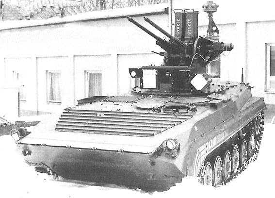
On the roof of the reinforced hull, a 30 mm calibre PLK, a gunner's turret and a sighting turret were placed in unison. The gun turret carried a 30 mm double-cannon launcher and the first stage antenna system of a passive radar angular system (PRUS) designed for coarse aiming into the direction and source of the signal. The PRUS antenna carrier was folded down in the transport position. The working pattern actually had a 30 mm PLDvK vz. 53/59 top tube installed. No modifications were made to the guns (it was planned to replace them with another type in the future). Modifications were made to the rifle, resulting from a change in the method of operation. Basically, everything related to manual control and aiming was removed and what was required by the fire control system was added (servo motors with precision gears, aiming sensors, limit switches and shot sensors). The sighting turret was mounted on a metering bearing taken from the 30 mm PLDvK vz. 53/59 and had the possibility of completely independent movement with respect to the gun turret. Reconnaissance and sighting instruments were installed on the sighting turret. In the front part, an optical sight was mounted on flexible mounts, created by modifying a prototype sight from the development of the VYDRA system. The optical sight had more or less a function for visual reconnaissance and as a spare sight. The commander was able to check the accuracy of the operator's tracking and observe the results of the firing. On the side walls of the sighting turret there were bearings for the cradles of other instruments. On the left side (in the direction of firing), a pair of antennas of the targeting part of the PRUS was placed in a common housing. On the right side, the laser rangefinder and the camera of the vidicon type TV sight. The TV sight was the basic targeting device. In the cage structure below the sighting turret was the commander's and gunner's station. Its seat was taken from BVP-1 and rotated with the turret. In addition to the optical sight, this station had a duplicate SRS control, a PRUS indicator, a call box for external and internal communications, a SRS signal and control console, and an operator's station. The fire control system of the STROP complex consisted of reconnaissance assets, targeting assets, range finder, computer assets and other sensors. The reconnaissance asset was a passive radar rangefinder system (PRRS). The PRRS operated by receiving signals from the on-board radars of the incoming aircraft, detecting the direction of targets and analysing these signals to identify them.
The system was two-stage: - the first stage had a higher sensitivity, operated omnidirectionally and detected targets and their azimuth. Its antenna system was mounted on a column mount on the gun's hull. - The second stage's task was to refine the azimuth of the selected target, determine its position angle, automatically lock on to it and make a preliminary identification. The second stage antenna system was mounted on a targeting turret on a common square shaft with a TV sight camera and laser rangefinder
The targeting system consisted of a TV sight and an optical sight. The use of the TV sight as the main sighting device allowed the operator's workstation to be placed in the hull of the vehicle, thus creating the best conditions for him to sensitively operate the control stick while tracking the target, without the distraction of the turret rotation. In addition, prerequisites were created for the later alternative use of cameras operating in different spectral regions and thus allowing the operation of the complex even in poor visibility conditions. In addition to the above-mentioned fundamental benefits of the TV sight, the possibility to display on the monitor screen, together with the observed scene, other information from the SRS and to record everything by video recorder was used during the tests of the complex. The video recording was then one of the main documents for the evaluation of the operator's activity and the whole complex as well as the results of the shooting. The computing centre of the asset consisted of two main computers and other auxiliary means. Based on the assumption of straightforward uniform motion of the target, it calculated its expected position, to which it guided the targeting turret. The operator could use these commands to use the control stick to correct deviations of the computer's prediction of the target's position from reality. That is, the fire control system of the STROP complex allowed semi-automatic target tracking. In connection with this issue, research work was initiated on automatic target tracking and processing of the digitized signal from the TV sight camera, which was to be prospectively used in the complex. Additional computers were integrated into the PRUS, laser rangefinder and servo systems. The gunnery turret was fully computer controlled in combat mode, in line with the targeting turret. Once the firing elements were calculated, the gunnery turret was then controlled independently of the targeting turret (which continued to track the target) with appropriate gun overrun.
The operator's station was located at the right rear of the fighting compartment BVP-1. In its central part there was a TV sight monitor and a console A detailed view of the rear of the operator's turret (compared to the commander's console) with wider possibilities of controlling and testing the whole complex, with a counter of fired rounds and a preset number of rounds in a batch. The hull of the vehicle also housed the SRP computer blocks, the electronics blocks for controlling the servomotors, and the batteries and inverters for powering the weapons superstructure. Source system The specified velocities of the targets against which the kit was to operate implied considerable requirements for the dynamics of the servo systems (100 o.s, 100 o.s-2) and the corresponding servo system performance. This in turn was reflected in the requirements for the source system, which had to deliver significant peak power. Conventional 24 VDC lead-acid batteries were used as the basic power supply element of the SRS, recharged from a power station. It was envisaged to install them in the vehicle, but the working model built was powered from an off-board power pack and alternatively from the industrial grid. Due to favourable building conditions and operational availability, a gas turbine driving the power plant was envisaged as the final solution. Development work on this was started but stopped at an early stage by a decision of the higher-ups. The turret's servo systems were powered by 115 V at 400 Hz with a peak power of 4 to 5 kVA provided by inverters.
The complex set-up required thorough testing. Testing of the complex then included untesting individual subsystems, verifying the links between subsystems in simulated situations, verifying the operation of the entire system while tracking and firing at real ground and air targets, and ending with live firing at ground and towed air targets. In total, over 450 tests were conducted, for which aircraft and helicopters of various types performed more than 300 passes. The main parameters of the functional pattern confirmed by the tests The parameters of the cannons remained identical to those of the 30 mm PLDvK vz. 53/59 in terms of their performance and firing accuracy (no modifications were made to the cannons, as analyses showed that the most effective would be a later replacement of the cannon type). The aiming range of the guns and sights was from -5 to +80, the range of sighting was 180 to either side of the longitudinal axis, the sight turret could move 25 to either side of the gun turret position. The maximum angular velocities of the turrets were 100.s in sighting, 60.s in square. The range of the TV sight and rangefinder was 7 km (under ideal visibility conditions, the TV sight could track MiG-21 up to 11 km). Firing could be initiated after 6 sec from target acquisition by the TV sight. The RCS allowed to open fire on an approaching target at a range of 4,000 meters. However, firing with the considered missile effect and cannon dispersion was effective at distances of 1,500-2,000 meters. After the first trials in 1984, necessary modifications were made on the basis of the experience gained (but not in the concept of the kit) and further trials were carried out the following year. The chassis used BVP-1 (with six running wheels) is not sufficient for its load capacity and a version with seven running wheels or a wheeled chassis will have to be used in the future.
Despite the fact that the working model did not achieve the results in all details according to the original ideas, the basic concept of the kit and especially the proposed fire control system were confirmed. On the basis of the tests it was possible to refine the specification for the development of the individual subsystems. This kit formed a solid basis for the continued development of PL kits.
Contractor.
Technicko-taktická data Weight 15 170 kg
Dimensions: - Length: 6 740 mm - Width: 2 940 mm - Height (in marching position): 2 700 mm - Height (in combat position): 3 575 mm
Bearing : -5° to +80° Bearing: ±180°
Zdroj 1) Martinec, J.: STROP anti-aircraft vehicle, ATM 2/1997, pp. 18-21, ISSN1210-2849 2) Martinec, J.: STROP anti-aircraft vehicle, ATM 3/1997, pp. 18-21, ISSN1210-2849
Period
-
Type
-
Camouflage
-
Country
-
Production No.
-
Poznávací značka / evidenční číslo
-
Tactical marking
-
Name
-
Unit
-
Date (DD.MM.RRRR)
-
Author
-
Print size / 300 DPI
-
Published with authors permit
-
Author Website
-
(ATM)
URL : https://www.valka.cz/CZK-STROP-t30025#117627
Version : 0
...
Period
-
Type
-
Camouflage
-
Country
-
Production No.
-
Poznávací značka / evidenční číslo
-
Tactical marking
-
Name
-
Unit
-
Date (DD.MM.RRRR)
-
Author
-
Print size / 300 DPI
-
Published with authors permit
-
Author Website
-
(ATM)
URL : https://www.valka.cz/CZK-STROP-t30025#117630
Version : 0
Diskuse
Further development of this vehicle in the 1980s and 1990s saw the creation of a new prototype of the STROP complex - the armoured T-815 chassis used in the ShKH Dana (later upgraded to Ondava and Zuzana), with 2 interlocking 30 mm 2A38 guns instead of the 30 mm PldvK. Missile armament consisted initially of 2 S-2M missiles, later up to 4 IGLA missiles. The system used the most modern electronic means available in the Czechoslovak Socialist Republic. Since after 1989 the lag of electronic systems developed in the CSSR in relation to the rest of the world was already too great, further development was focused on the incorporation of radio-electronic systems of foreign manufacture - French and Israeli companies, among others, cooperated on the system. At least 2 prototypes were produced, which were divided between the Czech and Slovak Republics after the division of the CSFR. In Slovakia, the development continued and resulted in the BRAMS hybrid set, in the Czech Republic in the STROP II set.
URL : https://www.valka.cz/CZK-STROP-t30025#140227
Version : 0
Reklama
....
Period
-
Type
-
Camouflage
-
Country
-
Production No.
-
Poznávací značka / evidenční číslo
-
Tactical marking
-
Name
-
Unit
-
Date (DD.MM.RRRR)
-
Author
-
Print size / 300 DPI
-
Published with authors permit
-
Author Website
-
URL : https://www.valka.cz/CZK-STROP-t30025#141786
Version : 0
Similar modifikácia ako Czechoslovak CEILING were aj on the Kube - right here..
URL : https://www.valka.cz/CZK-STROP-t30025#191161
Version : 0
Join us
We believe that there are people with different interests and experiences who could contribute their knowledge and ideas. If you love military history and have experience in historical research, writing articles, editing text, moderating, creating images, graphics or videos, or simply have a desire to contribute to our unique system, you can join us and help us create content that will be interesting and beneficial to other readers.